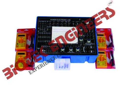
Product Description
Power Electronics Lab
Biotek Engineers is manuufacture,exporters & suppliers of : Power Electronics Lab
These products find applications in alarm circuit, lamp flasher, rectifiers, choppers and inverter.
Technical Specifications:
DC power supply on board:
- ± 5V at 100mA
- ± 12V at 150mA
- ± 15V at 50mA
- ± 35V at 50mA
Experiments on board using breadboard:
- To study the characteristics of SCR and plot its V-I characteristics
- To study the gate control characteristics of SCR and It's graph
- To study the characteristics of UGT and calculate interbase resistance and intrinsic standoff ratio
- To study the characteristics of MOSFET
- To study the characteristics of IGBT
- To study the characteristics of DIAC and plot its V-I characteristics curve
- To study the V-I characteristics of TRIAC
- To study the characteristics of PUT
- To study of class B commutation circuit
- To study of class C commutation circuit
- To study of class D commutation circuit
- To study of class F commutation circuit
- To study the resistor triggering circuit
- To study the resistor-capacitor triggering circuit (Half wave)
- To study the resistor-capacitor triggering circuit (Full wave)
- To study the triggering of SCR using UJT
- To study the triggering of SCR using 555 IC
- To study the triggering of SCR using Op-Amp 74I IC
- To study of the ramp and pedestal triggering using anti-parallel SCR in AC load
- To study of the UJT relaxation oscillator
- To study of the voltage commutated chopper
- To study of the Bedford inverter
- To study of the single phase PWM inverter using MOSFET
- To study of the single phase PWM inverter using IGBT
- To study the half-wave controlled rectifier with resistive load
- To study the half wave controlled rectifier with RL load
- To study the full-wave controlled rectifier (mid-point configuration) with resistive load
- To study the full-wave controlled rectifier (mid point configuration) with RL load
- To study the fully controlled bridge rectifier with resistive load
- To study the fully controlled bridge rectifier with RL load
AC power supply on board:
- 18V - 0V - 18V at 50mA
- 15V - 0V - 15V at 50mA
- Triggering circuit on board: 5 gate signal output
- Frequency range: 40Hz to 900Hz Variable
- Amplitude: 12V
- PWM control of G1,G2,G3 and G4 duty cycle control of “Gate” signal is 0 to 100%
- Single phase rectifier: Firing angle control 0°-180° variables
- Firing circuit on board: Four gate signal output with isolation
- SCR assembly: 4 SCRs 2P4M, 600V,2A
- Power devices: IGBT-G4BC20S, MOSFET-IRF540, UJT-2N2646, DIAC-DB3, TRIAC-BT136, PUT-2N6027
- Circuit components on board: Capacitor 0.01uF, 0.047uF , 0.1uF, 0.33uF, 1uF/63V(4Nos.) 2.2uF/50V
- Diode 1N4007 (8Nos.)
- Zener Diode 9V (1Nos.)
- Inductors 10mH, (1Nos.), 68mH (2Nos.)
- Load resistance 120E, 270E, 1K, 2K2, each 5W
- Resistance on board (½ W) 22E/5W, 100E/2W, 220E/2W
- Resistance on board(1/4W) 10K (3Nos.), 22K,33K,47K,
- Potentio meter 4K7(2Mos.), 1M(1Nos.)
- Pulse transformer on board: 2 Nos. PT4502, 1:1 and one is PT4503 1:1:1
- Toggle switch: SPST (1Nos.)
- Power requirements: 220V ±10%, 50Hz